引言
随着现代硬件设计的复杂性不断增加,传统的硬件描述语言已难以满足快速开发和高效验证的需求。Chisel(Constructing Hardware in Scala)作为一种基于 Scala 的硬件构建语言,结合了面向对象和函数式编程以及强大的类型系统,为设计者提供了更灵活的设计方式。同时,CIRCT(Circuit IR Compiler Toolchain)作为一个开源编译器基础设施,进一步增强了 Chisel 的功能,使得从硬件描述到最终实现的过程更加高效。本文将探讨 Chisel 与 CIRCT 的无缝集成,包括它们的发展历程、转换路线、细节示例及实际应用。
Chisel 历史背景
2012 年,UC Berkeley 在计算机体系结构领域顶级会议 DAC(Design Automation Conference)上发表了 Chisel: Constructing Hardware in a Scala Embedded Language 一文。其目的在于,通过引入面向对象和函数式编程、类型安全、类型推断以及参数化等,解决传统 Verilog 和 VHDL 在复杂电路设计中的局限性,例如:
- 基于仿真的语义:Verilog 和 VHDL 最初是作为硬件仿真语言开发的,后来才被采用作为硬件综合的基础;
- 缺乏强有力的抽象功能:相较于现代编程语言,传统的 HDL 缺乏强大的抽象功能,这种限制使得重用组件变得困难;
- 设计空间探索挑战:高效的硬件设计需要对不同的系统微架构进行广泛的探索。然而,传统的 HDL 生成模块的能力有限,并且不太适合生成彻底设计空间探索所需的高度参数化的模块生成器。
而 Chisel 被设计为基于 Scala 的一个硬件电路生成语言的一系列函数库,这意味着 Chisel 允许设计者使用熟悉的编程结构,从而使得硬件设计更加灵活和可维护。其主要优势如下:
- 强大的语言:Scala 是一种非常强大的语言,具有对于构建电路生成器很重要的功能;
- 领域特定语言支持:专门为促进领域特定语言的创建而设计的,使其适合硬件描述;
- 与 JVM 的兼容:Scala 源码可被编译成能在 JVM 上运行的字节码,从而实现跨平台兼容性并利用现有的 Java 工具;
- 丰富的生态:Scala 拥有丰富的开发工具和集成开发环境生态系统,可提高生产力;
- 组成方式:Chisel 由一组 Scala 库组成,这些库定义了新的硬件数据类型,并提供了一系列例程,将硬件数据结构转换为快速的 C++ 模拟器或低级 Verilog,以便进行仿真或综合。
随着 Chisel 5 的发布,Chisel 从旧版 Scala FIRRTL 编译器(SFC)移至 MLIR FIRRTL 编译器(MFC),后者是 llvm/circt 项目的一部分。在此版本之后,SFC 不再维护。底层编译器技术的这一变更为 Chisel 引入了许多新的特性,如线性时间逻辑以及监测指定信号的变化 。不幸的是,Chisel 3 的测试库 ChiselTest 是围绕 SFC 构建的,因此很难在 Chisel 5 及更高版本中支持 ChiselTest。而后,由 Chisel 核心开发团队维护和使用的 ChiselSim 成为了 Chisel 5 及更高版本中经过批准的 ChiselTest 替代品。
Chisel 语言特性
我们在 Chisel 的历史背景中提到,Chisel 的推出是为了解决传统 Verilog 和 VHDL 在复杂电路设计中的局限性。接下来我们将从语言特性层面出发,探讨相较于 Verilog,Chisel 有哪些优势,如下:
- 参数化模块:
- Chisel 允许设计者轻松创建参数化模块,这意味着可以在实例化模块时动态传递参数,使设计者可以根据不同的需求生成不同配置的硬件组件。
- 在 Verilog 中,虽然可以通过宏和
generate语句实现类似的功能,但其灵活性和可读性通常较差,且不如 Chisel 直观。
- 强类型检查:
- Chisel 基于 Scala 的强类型系统,提供了多种硬件数据类型(如
UInt、SInt、Bool等),并在编译时进行严格的类型检查。这有助于捕获潜在的错误并提高代码质量。 - Verilog 的数据类型相对宽松,许多操作在编译时不会进行严格检查,尤其是 Verilog 中的
reg和logic类型。
- Chisel 基于 Scala 的强类型系统,提供了多种硬件数据类型(如
- 面向对象编程:
- Chisel 支持面向对象编程,设计者可以使用类、继承和多态等概念来构建复杂的硬件模块。这种方法提高了代码的复用性和可维护性。
- Verilog 是一种过程式语言,不支持面向对象编程,这使得实现复杂结构时需要更多的手动管理和重复代码。
- 函数式编程特性:
- Chisel 允许使用高阶函数和集合操作,如映射、过滤,使得处理数据变得更加高效。例如,可以轻松地对向量中的每个元素进行操作,而不需要显式地编写循环。
- Verilog 缺乏函数式编程特性,数据处理通常依赖于手动循环和条件语句,代码可读性较差。
- 模块与接口管理:
- Chisel 引入了
Bundle类,用于将多个信号组合成一个复合信号,并且可以通过Flipped方法轻松反转接口方向。这种方式简化了接口管理,使得设计更加清晰。 - 在 Verilog 中,接口管理相对繁琐,需要手动定义每个信号,并且没有类似
Flipped的方法来简化接口方向的处理。
- Chisel 引入了
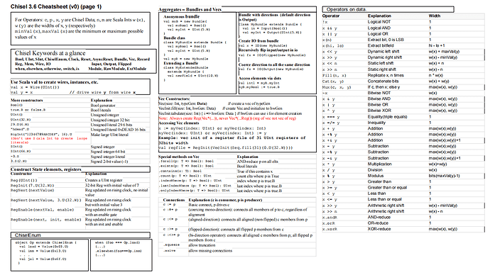
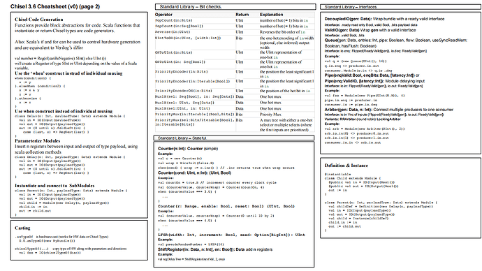
Chisel Cheat Sheet 如下:
FIRRTL 发展历程
FIRRTL(Flexible Intermediate Representation for RTL)作为 Chisel 项目的一部分,其概念最初于 2012 年由 UC Berkeley 提出。Chisel 旨在提供一种更高效的硬件设计方法,而 FIRRTL 则作为其核心组件,提供了一个灵活的中间表示形式,用于支持各种电路转换和优化操作。
在 2014 年,FIRRTL 作为一个开源项目正式发布,并随着 Chisel 的流行逐渐被广泛应用于硬件设计中。其设计目标是为电路设计提供一个灵活的中间表示形式,使得开发者能够在不同层次上进行优化,而无需直接操作底层门级逻辑。此外,该项目还支持将 .fir 文件转换为 Verilog,并提供了许多有用的 Pass 和基础设施。FIRRTL 项目也支持与其它工具的集成,如 Treadle(用于仿真和测试电路行为的解释器)。
随着技术的发展,于 2020 年,FIRRTL 项目的核心开发人员建议用户转向 CIRCT。CIRCT 是一个基于 MLIR 的新项目,旨在进一步扩展和优化硬件设计流程(详情请查看 CIRCT - 基于 MLIR 的电路编译器和工具链)。CIRCT 中的 FIRRTL 方言旨在为 Chisel 生成的常用 FIRRTL IR 子集提供 SFC 的直接替代,以及提供对 SFC 注释的支持。为了实现这些目标,FIRRTL 方言几乎完全遵循 FIRRTL IR 和 SFC 注释的标准。该方言也允许存在未定义的行为,在这种情况下,该方言及其 Pass 会选择 SFC 注释形式对这种未定义行为进行解释。
Chisel 和 FIRRTL 的发展背景与现代硬件设计的复杂性密切相关。随着集成电路技术的发展,芯片架构日益复杂,传统的 HDL 及其工具面临着无法有效处理复杂设计的问题。因此,开发一种新的硬件语言和中间表示成为必然,这为硬件设计者提供了更为灵活的方案,以满足现代 FPGA 和 ASIC 设计的复杂性。
Chisel 转换路线
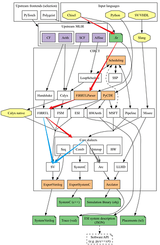
在 CIRCT 项目早期,由于 cycle-based 的 Arcilator 仿真器还处于规划开发阶段,当时仅存在 event-driven 的 llhd-sim 仿真器,而为了能使用 cycle-based 的开源仿真器 Verilator,Chisel 早期的转换路线是生成 SystemVerilog 代码。在 Arcilator 被成功开发出来之后,Chisel 转换路线被分为了两条:一条是早期的生成 SystemVerilog 代码路线;另外一条是下降到 Core 方言层之后,直接由 Arcilator 仿真器进行仿真。下图中各颜色箭头解释如下:
- 红色:两条转换路线共用;
- 蓝色:为了生成 SystemVerilog 的转换路线;
- 灰色:Chisel 代码被下降到 Core 方言层之后,直接交由 Arcilator 处理的转换路线。
FIRRTL 方言:该方言用于映射 Chisel 代码中的特性,以及支持由 Chisel 生成的 CHIRRTL 风格的 IR,CHIRRTL 方言包含可以降低为 FIRRTL IR 的高层级内存定义。FIRRTL 方言还支持解析 SFC 注释文件并将其转换为 Operations 或 Attributes。
Core 方言:这里的 Core 方言指的是 Seq、Comb 和 HW 方言;
- Seq:用于表示带复位信号和使能信号的寄存器逻辑。例如
seq.comreg.ce用于描述具有使能信号和复位信号的同步时序逻辑,而seq.firreg则表示带有复位信号的同步或异步时序逻辑。 - HW:专用于表示硬件设计中的公共特性。该方言定义的 Operations 不涉及组合逻辑、时序逻辑和线网之间的连接逻辑,因此具有高度的通用性,并能够与其他方言灵活结合使用。这使得 HW 方言不依赖于特定的硬件语言。例如,它可以有效地表示硬件中的 module、instance 和 port;
- Comb:与 HW 方言类似,提供一种不依赖于特定硬件语言的通用表示方式。专注于表示硬件电路中的组合电路,其设计理念强调简洁性,力求用更少的 Operations 表达更多的功能。例如,通过将 x 与全 1 进行异或运算,可以有效地表示一元位运算符(~x)。
SV 方言:该方言旨在直接对 SystemVerilog 语言的语法进行建模,并通过 ExportVerilog pass 轻松生成 SystemVerilog。由于该方言专注于输出 SystemVerilog,因此生成的 IR 采用“AST”风格的表示形式。此外,该方言可以与 Core 层的其他方言混合使用,因此它并不具备独立的组合逻辑、时序逻辑以及模块等常见功能。
Arc 方言:专注于表示硬件电路中信号的变化状态、时钟域、时钟树;
Chisel 细节举例
用于 Chisel 转换路线的工具
Chisel 转换路线主要分为两个阶段,一个在 CIRCT 项目之外的转换,即从 Scala 源码转换为.fir 文件;另一个是在 CIRCT 项目内部的转换,即将.fir 文件当做源文件,执行后续的下降转换。两个阶段涉及到的工具如下:
- sbt(Simple Build Tool):sbt 是一个用于构建和管理 Scala 项目的工具,使用该工具可将 Scala 源代码转换为.fir 文件;
- circt-translate:该工具中的
import-firrtl选项可将.fir 文件转换成 FIRRTL IR,而--export-firrtl正好与之相反。import-verilog选项使得用户能够方便地将.fir 文件导入到 CIRCT 环境中,为后续的处理和优化奠定基础; - circt-opt:该工具可用于单步执行方言与方言直接的转换,也可用于单个方言之内的优化。由于与 FIRRTL 相关的 Pass 十分之多,故在此不进行额外举例说明。这些功能强大的优化工具能够帮助用户提高设计效率,确保生成的电路在性能和资源利用率方面达到最佳状态;
- firtool:该工具可将众多 FIRRTL 方言层的优化 Pass 以及 FIRRTL 向 SV 及 Core 方言转换的 Pass 集成在一起,通过某几个选项即可灵活地满足用户的需求,如不同的输入、输出文件类型。
FIRRTL 方言层中的优化 Pass
由于 FIRRTL 方言层中的优化 Pass 数量众多,以下仅列举几个典型的优化 Pass,以便更好地理解其功能和作用:
--firrtl-dedup:用于消除相同重复的模块实例化。在复杂的硬件设计中具有显著的优势,能够大幅度减少生成的 MLIR 文件的大小,从而加快仿真速度。这一优化过程通过消除冗余代码和重复逻辑,提升了整体设计的效率。
执行 Pass 之前:对同一个 Empty 模块进行实例化时,生成了三份重复的 Empty0、Empty1、Empty2。
firrtl.circuit "Empty" {
  firrtl.module private @Empty0(in %i0: !firrtl.uint<1>) { }
  firrtl.module private @Empty1(in %i1: !firrtl.uint<1>) { }
  firrtl.module private @Empty2(in %i2: !firrtl.uint<1>) { }
  firrtl.module @Empty() {
    %e0_i0 = firrtl.instance e0 @Empty0(in i0: !firrtl.uint<1>)
    %e1_i1 = firrtl.instance e1 @Empty1(in i1: !firrtl.uint<1>)
    %e2_i2 = firrtl.instance e2 @Empty2(in i2: !firrtl.uint<1>)
  }
}
执行 Pass 之后:将三份重复的 Empty 模块合并为一个。
firrtl.circuit "Empty" {
    firrtl.module private @Empty0(in %i0: !firrtl.uint<1>) {
    }
    firrtl.module @Empty() {
      %e0_i0 = firrtl.instance e0 @Empty0(in i0: !firrtl.uint<1>)
      %e1_i0 = firrtl.instance e1 @Empty0(in i0: !firrtl.uint<1>)
      %e2_i0 = firrtl.instance e2 @Empty0(in i0: !firrtl.uint<1>)
    }
}
--firrtl-lower-chirrtl:用于推断用 CHIRRTL 方言定义的高层级内存,并将其转换为 FIRRTL 方言。使得 CHIRRTL 与 FIRRTL 之间的转换更加顺畅,增强了 Chisel 生成的代码与 FIRRTL 生态系统中其他工具和 Pass 的兼容性。
执行 Pass 之前:用 CHIRRTL 方言定义的高层级内存
firrtl.module @InferWrite(in %cond: !firrtl.uint<1>, in %clock: !firrtl.clock, in %addr: !firrtl.uint<8>, in %in : !firrtl.uint<1>) {
  %ram = chirrtl.combmem : !chirrtl.cmemory<uint<1>, 256>
  %ramport_data, %ramport_port = chirrtl.memoryport Infer %ram {name = "ramport"} : (!chirrtl.cmemory<uint<1>, 256>) -> (!firrtl.uint<1>, !chirrtl.cmemoryport)
  firrtl.when %cond : !firrtl.uint<1> {
    chirrtl.memoryport.access %ramport_port[%addr], %clock : !chirrtl.cmemoryport, !firrtl.uint<8>, !firrtl.clock
  }
  firrtl.connect %ramport_data, %in : !firrtl.uint<1>, !firrtl.uint<1>
  firrtl.connect %ramport_data, %in : !firrtl.uint<1>, !firrtl.uint<1>
}
执行 Pass 之后:将 CHIRRTL 定义的高层级内存转换为 FIRRTL 方言
firrtl.module @InferWrite(in %cond: !firrtl.uint<1>, in %clock: !firrtl.clock, in %addr: !firrtl.uint<8>, in %in: !firrtl.uint<1>) {
      %invalid_ui1 = firrtl.invalidvalue : !firrtl.uint<1>
      %c1_ui1 = firrtl.constant 1 : !firrtl.uint<1>
      %invalid_clock = firrtl.invalidvalue : !firrtl.clock
      %c0_ui1 = firrtl.constant 0 : !firrtl.uint<1>
      %invalid_ui8 = firrtl.invalidvalue : !firrtl.uint<8>
      %ram_ramport = firrtl.mem Undefined {depth = 256 : i64, name = "ram", portNames = ["ramport"], readLatency = 0 : i32, writeLatency = 1 : i32} : !firrtl.bundle<addr: uint<8>, en: uint<1>, clk: clock, data: uint<1>, mask: uint<1>>
      %0 = firrtl.subfield %ram_ramport[addr] : !firrtl.bundle<addr: uint<8>, en: uint<1>, clk: clock, data: uint<1>, mask: uint<1>>
      firrtl.matchingconnect %0, %invalid_ui8 : !firrtl.uint<8>
      %1 = firrtl.subfield %ram_ramport[en] : !firrtl.bundle<addr: uint<8>, en: uint<1>, clk: clock, data: uint<1>, mask: uint<1>>
      firrtl.matchingconnect %1, %c0_ui1 : !firrtl.uint<1>
      %2 = firrtl.subfield %ram_ramport[clk] : !firrtl.bundle<addr: uint<8>, en: uint<1>, clk: clock, data: uint<1>, mask: uint<1>>
      firrtl.matchingconnect %2, %invalid_clock : !firrtl.clock
      %3 = firrtl.subfield %ram_ramport[data] : !firrtl.bundle<addr: uint<8>, en: uint<1>, clk: clock, data: uint<1>, mask: uint<1>>
      firrtl.matchingconnect %3, %invalid_ui1 : !firrtl.uint<1>
      %4 = firrtl.subfield %ram_ramport[mask] : !firrtl.bundle<addr: uint<8>, en: uint<1>, clk: clock, data: uint<1>, mask: uint<1>>
      firrtl.matchingconnect %4, %invalid_ui1 : !firrtl.uint<1>
      firrtl.when %cond : !firrtl.uint<1> {
        firrtl.matchingconnect %0, %addr : !firrtl.uint<8>
        firrtl.matchingconnect %1, %c1_ui1 : !firrtl.uint<1>
        firrtl.matchingconnect %2, %clock : !firrtl.clock
        firrtl.matchingconnect %4, %c0_ui1 : !firrtl.uint<1>
      }
      firrtl.matchingconnect %4, %c1_ui1 : !firrtl.uint<1>
      firrtl.connect %3, %in : !firrtl.uint<1>
      firrtl.matchingconnect %4, %c1_ui1 : !firrtl.uint<1>
      firrtl.connect %3, %in : !firrtl.uint<1>
    }
--firrtl-infer-resets:通过自动推断复位信号的同步或异步特性,为 FIRRTL 方言带来了显著优势。这不仅简化了设计过程,提高了仿真和综合效率,还增强了代码的可读性和复杂设计的支持能力,为硬件开发提供了更强大的工具。
执行 Pass 之前:用 SFC 注释的形式描述异步时序逻辑。
firrtl.circuit "Top" {
  firrtl.module @Top(in %clock: !firrtl.clock, in %reset: !firrtl.asyncreset) attributes {
    portAnnotations = [[],[{class = "circt.FullResetAnnotation", resetType = "async"}]]} {
    %reg_uint = firrtl.reg %clock : !firrtl.clock, !firrtl.uint
    %reg_sint = firrtl.reg %clock : !firrtl.clock, !firrtl.sint
    %reg_bundle = firrtl.reg %clock : !firrtl.clock, !firrtl.bundle<a: uint<8>, b: bundle<x: uint<8>, y: uint<8>>>
    %reg_vector = firrtl.reg %clock : !firrtl.clock, !firrtl.vector<uint<8>, 4>
  }
}
执行 Pass 之后:处理 SFC 注释,生成相应的 FIRRTL 方言。
module {
  firrtl.circuit "Top" {
    firrtl.module @Top(in %clock: !firrtl.clock, in %reset: !firrtl.asyncreset [{class = "circt.FullResetAnnotation", resetType = "async"}]) attributes {annotations = [{class = "circt.FullResetAnnotation"}]} {
      %c0_ui = firrtl.constant 0 : !firrtl.const.uint
      %reg_uint = firrtl.regreset %clock, %reset, %c0_ui : !firrtl.clock, !firrtl.asyncreset, !firrtl.const.uint, !firrtl.uint
      %c0_si = firrtl.constant 0 : !firrtl.const.sint
      %reg_sint = firrtl.regreset %clock, %reset, %c0_si : !firrtl.clock, !firrtl.asyncreset, !firrtl.const.sint, !firrtl.sint
      %0 = firrtl.wire : !firrtl.const.bundle<a: uint<8>, b: bundle<x: uint<8>, y: uint<8>>>
      %c0_ui8 = firrtl.constant 0 : !firrtl.const.uint<8>
      %1 = firrtl.subfield %0[a] : !firrtl.const.bundle<a: uint<8>, b: bundle<x: uint<8>, y: uint<8>>>
      firrtl.matchingconnect %1, %c0_ui8 : !firrtl.const.uint<8>
      %2 = firrtl.wire : !firrtl.const.bundle<x: uint<8>, y: uint<8>>
      %3 = firrtl.subfield %2[x] : !firrtl.const.bundle<x: uint<8>, y: uint<8>>
      firrtl.matchingconnect %3, %c0_ui8 : !firrtl.const.uint<8>
      %4 = firrtl.subfield %2[y] : !firrtl.const.bundle<x: uint<8>, y: uint<8>>
      firrtl.matchingconnect %4, %c0_ui8 : !firrtl.const.uint<8>
      %5 = firrtl.subfield %0[b] : !firrtl.const.bundle<a: uint<8>, b: bundle<x: uint<8>, y: uint<8>>>
      firrtl.matchingconnect %5, %2 : !firrtl.const.bundle<x: uint<8>, y: uint<8>>
      %reg_bundle = firrtl.regreset %clock, %reset, %0 : !firrtl.clock, !firrtl.asyncreset, !firrtl.const.bundle<a: uint<8>, b: bundle<x: uint<8>, y: uint<8>>>, !firrtl.bundle<a: uint<8>, b: bundle<x: uint<8>, y: uint<8>>>
      %6 = firrtl.wire : !firrtl.const.vector<uint<8>, 4>
      %c0_ui8_0 = firrtl.constant 0 : !firrtl.const.uint<8>
      %7 = firrtl.subindex %6[0] : !firrtl.const.vector<uint<8>, 4>
      firrtl.matchingconnect %7, %c0_ui8_0 : !firrtl.const.uint<8>
      %8 = firrtl.subindex %6[1] : !firrtl.const.vector<uint<8>, 4>
      firrtl.matchingconnect %8, %c0_ui8_0 : !firrtl.const.uint<8>
      %9 = firrtl.subindex %6[2] : !firrtl.const.vector<uint<8>, 4>
      firrtl.matchingconnect %9, %c0_ui8_0 : !firrtl.const.uint<8>
      %10 = firrtl.subindex %6[3] : !firrtl.const.vector<uint<8>, 4>
      firrtl.matchingconnect %10, %c0_ui8_0 : !firrtl.const.uint<8>
      %reg_vector = firrtl.regreset %clock, %reset, %6 : !firrtl.clock, !firrtl.asyncreset, !firrtl.const.vector<uint<8>, 4>, !firrtl.vector<uint<8>, 4>
    }
  }
}
实战举例:Johnson 计数器
Scala 源码:
// 将此文件命名为 JohnsonCounter.scala

import chisel3._
import chisel3.util._

class JohnsonCounter(n: Int) extends Module {
  val io = IO(new Bundle {
    val clk = Input(Clock())           // 时钟输入
    val reset = Input(Bool())          // 复位信号
    val count = Output(UInt(n.W))      // 输出计数值
  })

  // 创建一个寄存器数组,用于存储计数器状态
  val reg = RegInit(0.U(n.W))

  // Johnson计数器的逻辑
  when(io.reset) {
    reg := 0.U // 在复位时清零
  }.otherwise {
    reg := Cat(~reg(n-1), reg(n-1, 1)) // 将最后一位取反并移位
  }

  io.count := reg // 输出当前计数值
}

// 用于测试的对象
object JohnsonCounter extends App {
  chisel3.Driver.execute(args, () => new JohnsonCounter(4)) // 创建一个4位的Johnson计数器
}
.fir 文件:
// RUN sbt "runMain JohnsonCounter"

FIRRTL version 2.0.0
circuit JohnsonCounter :
  module JohnsonCounter :
    input clock : Clock
    input reset : UInt<1>
    output io : { flip clk : Clock, flip reset : UInt<1>, count : UInt<4>}
    // 创建一个寄存器数组,用于存储计数器状态
    reg reg : UInt<4>, clock with :
      reset => (reset, UInt<4>("h0")) @[JohnsonCounter.scala 12:20]
    // 当触发复位信号时,将寄存器数组置为0
    when io.reset : @[JohnsonCounter.scala 15:18]
      reg <= UInt<1>("h0") @[JohnsonCounter.scala 16:9]
    else :
    // 否则执行取反移位逻辑
      node _T = bits(reg, 3, 3) @[JohnsonCounter.scala 18:20]
      node _T_1 = not(_T) @[JohnsonCounter.scala 18:16]
      node _T_2 = bits(reg, 3, 1) @[JohnsonCounter.scala 18:30]
      node _T_3 = cat(_T_1, _T_2) @[Cat.scala 30:58]
      reg <= _T_3 @[JohnsonCounter.scala 18:9]
    io.count <= reg @[JohnsonCounter.scala 21:12]
FIRRTL IR:
// RUN firtool --format=fir ~/JohnsonCounter.fir --ir-fir

module {
  firrtl.circuit "JohnsonCounter" {
    firrtl.module @JohnsonCounter(in %clock: !firrtl.clock, in %reset: !firrtl.uint<1>, in %io_clk: !firrtl.clock, in %io_reset: !firrtl.uint<1>, out %io_count: !firrtl.uint<4>) attributes {convention = #firrtl<convention scalarized>} {
      %c0_ui4 = firrtl.constant 0 : !firrtl.uint<4>
      %io_count_0 = firrtl.wire {name = "io_count"} : !firrtl.uint<4>
      firrtl.matchingconnect %io_count, %io_count_0 : !firrtl.uint<4>
      // %clock 是时钟信号
      // %reset 是复位信号
      // %c0_ui4 是复位值
      %reg = firrtl.regreset %clock, %reset, %c0_ui4 {firrtl.random_init_start = 0 : ui64} : !firrtl.clock, !firrtl.uint<1>, !firrtl.uint<4>, !firrtl.uint<4>
      // 取%reg的第3位
      %0 = firrtl.bits %reg 3 to 3 : (!firrtl.uint<4>) -> !firrtl.uint<1>
      %1 = firrtl.not %0 : (!firrtl.uint<1>) -> !firrtl.uint<1>
      // 取%reg的第1~3位
      %2 = firrtl.bits %reg 3 to 1 : (!firrtl.uint<4>) -> !firrtl.uint<3>
      // 连接运算
      %3 = firrtl.cat %1, %2 : (!firrtl.uint<1>, !firrtl.uint<3>) -> !firrtl.uint<4>
      // 根据信号变化为寄存器赋值
      %4 = firrtl.mux(%io_reset, %c0_ui4, %3) : (!firrtl.uint<1>, !firrtl.uint<4>, !firrtl.uint<4>) -> !firrtl.uint<4>
      firrtl.matchingconnect %reg, %4 : !firrtl.uint<4>
      firrtl.matchingconnect %io_count_0, %reg : !firrtl.uint<4>
    }
  }
}
Core IR:
// RUN firtool --format=fir ~/JohnsonCounter.fir --ir-hw -o ~/JohnsonCounter.mlir

module {
  hw.module @JohnsonCounter(in %clock : !seq.clock, in %reset : i1, in %io_clk : !seq.clock, in %io_reset : i1, out io_count : i4) {
    %true = hw.constant true
    %c0_i4 = hw.constant 0 : i4
    // %4 代表触发时钟信号,但不触发复位信号时的值
    // %clock 代表时钟信号
    // sync 代表同步逻辑
    // %reset 代表复位信号
    // %c0_i4 代表触发复位信号时的复位值
    %reg = seq.firreg %4 clock %clock reset sync %reset, %c0_i4 {firrtl.random_init_start = 0 : ui64, sv.namehint = "reg"} : i4
    %0 = comb.extract %reg from 3 : (i4) -> i1  // 取 %reg的第3位
    %1 = comb.xor bin %0, %true : i1
    %2 = comb.extract %reg from 1 : (i4) -> i3  // 取 %reg的1~3位
    %3 = comb.concat %1, %2 : i1, i3
    %4 = comb.mux bin %io_reset, %c0_i4, %3 : i4
    hw.output %reg : i4
  }
  om.class @JohnsonCounter_Class(%basepath: !om.basepath) {
    om.class.fields
  }
}
随着 Arcilator 的发布,我们现在可以采用新的方法,即通过 JIT 技术在生成 Core IR 时进行仿真测试。使用这种方式,我们能够更高效地进行仿真,并实时输出结果。就像仿真用 SystemVerilog 实现的 Johnson 计数器那样,为其添加 func.func @XXX 。接着,通过执行arcilator %s --run --jit-entry=xxx命令进行仿真结果的输出打印。例如:
Arcilator 仿真:
// RUN arcilator ~/JohnsonCounter.mlir --run --jit-entry=main

  hw.module @JohnsonCounter(in %clock : !seq.clock, in %reset : i1, in %io_clk : !seq.clock, in %io_reset : i1, out io_count : i4) {
    %true = hw.constant true
    %c0_i4 = hw.constant 0 : i4
    %reg = seq.firreg %4 clock %clock reset sync %reset, %c0_i4 {firrtl.random_init_start = 0 : ui64, sv.namehint = "reg"} : i4
    %0 = comb.extract %reg from 3 : (i4) -> i1
    %1 = comb.xor bin %0, %true : i1
    %2 = comb.extract %reg from 1 : (i4) -> i3
    %3 = comb.concat %1, %2 : i1, i3
    %4 = comb.mux bin %io_reset, %c0_i4, %3 : i4
    hw.output %reg : i4
  }
  om.class @JohnsonCounter_Class(%basepath: !om.basepath) {
    om.class.fields
  }

// main函数(与--jit-entry=main中的main保持一致),内部实现类似testbench,只不过以.mlir格式存在
func.func @main() {
  // 1 bit的 0,1  后续用于模拟时钟信号与复位信号
  %zero = arith.constant 0 : i1
  %one = arith.constant 1 : i1

  %clk0 = seq.to_clock %zero
  %clk1 = seq.to_clock %one

  // %lb 表示for循环中的起始值
  // %ub 表示for循环中的终值
  // %step 表示for循环中的步长
  %lb = arith.constant 0 : index
  %ub = arith.constant 10 : index
  %step = arith.constant 1 : index

  %rst_num = arith.constant 4 :index  // 用于表示循环条件 i = 4时,触发复位信号
  %locked_num = arith.constant 9 : index  // 后续用于表示 i != 9时,时钟信号才发生变化

  arc.sim.instantiate @JohnsonCounter as %model {
    // 获取输出端口 io_count,并输出其初始值
    %init_val = arc.sim.get_port %model, "io_count" : i4, !arc.sim.instance<@JohnsonCounter>
    arc.sim.emit "counter_initial_value", %init_val : i4

    // 循环10次
    scf.for %i = %lb to %ub step %step {
      // 将复位信号设置为低电平状态
      arc.sim.set_input %model, "reset" = %zero : i1, !arc.sim.instance<@JohnsonCounter>
      // 可以理解成保存设置,即更新(reset) 将复位信号设置为低电平状态 这个操作
      arc.sim.step %model : !arc.sim.instance<@JohnsonCounter>

      // 判断 i = 4 是否成立
      %cond = arith.cmpi eq, %i, %rst_num : index
      scf.if %cond {
        // 条件成立,将复位信号置为高电平,此时复位信号从低电平--->高电平跳转,计数器触发复位
        arc.sim.set_input %model, "reset" = %one : i1, !arc.sim.instance<@JohnsonCounter>
        arc.sim.step %model : !arc.sim.instance<@JohnsonCounter>
      }

      // 判断 i != 9 是否成立
      %cond1 = arith.cmpi ne, %i, %locked_num : index
      scf.if %cond1 {
        // 条件成立,时钟信号在每个cycle都执行从低电平--->高电平的跳变,计数器进行计数
        arc.sim.set_input %model, "clock" = %clk0 : !seq.clock, !arc.sim.instance<@JohnsonCounter>
        arc.sim.step %model : !arc.sim.instance<@JohnsonCounter>
        arc.sim.set_input %model, "clock" = %clk1 : !seq.clock, !arc.sim.instance<@JohnsonCounter>
        arc.sim.step %model : !arc.sim.instance<@JohnsonCounter>
      }
      // 读取输出端口 io_count,并输出计数值
      %counter_val = arc.sim.get_port %model, "io_count" : i4, !arc.sim.instance<@JohnsonCounter>
      arc.sim.emit "counter_value", %counter_val : i4
    }
  }
  return
}


仿真结果:
counter_initial_value = 0
counter_value = 8
counter_value = 4
counter_value = a
counter_value = 5
counter_value = 0    // 触发复位信号
counter_value = 8
counter_value = 4
counter_value = a
counter_value = 5
counter_value = 5    // 时钟信号未发生变化
而在早期阶段,Chisel 的仿真流程是通过将代码转换为 SystemVerilog 方言,然后生成 SystemVerilog 代码,最后利用 Verilator 进行仿真测试。生成 SystemVerilog 代码方法如下:
SV IR:
// RUN firtool --format=fir ~/JohnsonCounter.fir --ir-sv

module {
  sv.macro.decl @SYNTHESIS
  sv.macro.decl @VERILATOR
  emit.fragment @RANDOM_INIT_FRAGMENT {
    sv.verbatim "// Standard header to adapt well known macros for register randomization."
    sv.verbatim "\0A// RANDOM may be set to an expression that produces a 32-bit random unsigned value."
    sv.ifdef  @RANDOM {
    } else {
      sv.macro.def @RANDOM "$random"
    }
    sv.verbatim "\0A// Users can define INIT_RANDOM as general code that gets injected into the\0A// initializer block for modules with registers."
    sv.ifdef  @INIT_RANDOM {
    } else {
      sv.macro.def @INIT_RANDOM ""
    }
    sv.verbatim "\0A// If using random initialization, you can also define RANDOMIZE_DELAY to\0A// customize the delay used, otherwise 0.002 is used."
    sv.ifdef  @RANDOMIZE_DELAY {
    } else {
      sv.macro.def @RANDOMIZE_DELAY "0.002"
    }
    sv.verbatim "\0A// Define INIT_RANDOM_PROLOG_ for use in our modules below."
    sv.ifdef  @INIT_RANDOM_PROLOG_ {
    } else {
      sv.ifdef  @RANDOMIZE {
        sv.ifdef  @VERILATOR {
          sv.macro.def @INIT_RANDOM_PROLOG_ "`INIT_RANDOM"
        } else {
          sv.macro.def @INIT_RANDOM_PROLOG_ "`INIT_RANDOM #`RANDOMIZE_DELAY begin end"
        }
      } else {
        sv.macro.def @INIT_RANDOM_PROLOG_ ""
      }
    }
  }
  emit.fragment @RANDOM_INIT_REG_FRAGMENT {
    sv.verbatim "\0A// Include register initializers in init blocks unless synthesis is set"
    sv.ifdef  @RANDOMIZE {
    } else {
      sv.ifdef  @RANDOMIZE_REG_INIT {
        sv.macro.def @RANDOMIZE ""
      }
    }
    sv.ifdef  @SYNTHESIS {
    } else {
      sv.ifdef  @ENABLE_INITIAL_REG_ {
      } else {
        sv.macro.def @ENABLE_INITIAL_REG_ ""
      }
    }
    sv.verbatim ""
  }
  sv.macro.decl @ENABLE_INITIAL_REG_
  sv.macro.decl @ENABLE_INITIAL_MEM_
  sv.macro.decl @FIRRTL_BEFORE_INITIAL
  sv.macro.decl @FIRRTL_AFTER_INITIAL
  sv.macro.decl @RANDOMIZE_REG_INIT
  sv.macro.decl @RANDOMIZE
  sv.macro.decl @RANDOMIZE_DELAY
  sv.macro.decl @RANDOM
  sv.macro.decl @INIT_RANDOM
  sv.macro.decl @INIT_RANDOM_PROLOG_
  hw.module @JohnsonCounter(in %clock : i1, in %reset : i1, in %io_clk : i1, in %io_reset : i1, out io_count : i4) attributes {emit.fragments = [@RANDOM_INIT_REG_FRAGMENT, @RANDOM_INIT_FRAGMENT]} {
    %c0_i0 = hw.constant 0 : i0
    %true = hw.constant true
    %false = hw.constant false
    %c0_i4 = hw.constant 0 : i4
    %reg = sv.reg {sv.namehint = "reg"} : !hw.inout<i4>
    %0 = sv.read_inout %reg : !hw.inout<i4>
    %1 = comb.extract %0 from 3 : (i4) -> i1
    %2 = comb.xor bin %1, %true : i1
    %3 = comb.extract %0 from 1 : (i4) -> i3
    %4 = comb.concat %2, %3 : i1, i3
    %5 = comb.mux bin %io_reset, %c0_i4, %4 : i4
    sv.always posedge %clock {
      sv.if %reset {
        sv.passign %reg, %c0_i4 : i4
      } else {
        sv.passign %reg, %5 : i4
      }
    }
    sv.ifdef  @ENABLE_INITIAL_REG_ {
      sv.ordered {
        sv.ifdef  @FIRRTL_BEFORE_INITIAL {
          sv.verbatim "`FIRRTL_BEFORE_INITIAL"
        }
        sv.initial {
          sv.ifdef.procedural  @INIT_RANDOM_PROLOG_ {
            sv.verbatim "`INIT_RANDOM_PROLOG_"
          }
          sv.ifdef.procedural  @RANDOMIZE_REG_INIT {
            %_RANDOM = sv.logic : !hw.inout<uarray<1xi32>>
            %RANDOM = sv.macro.ref.expr.se @RANDOM() : () -> i32
            %6 = comb.extract %false from 0 : (i1) -> i0
            %7 = sv.array_index_inout %_RANDOM[%6] : !hw.inout<uarray<1xi32>>, i0
            sv.bpassign %7, %RANDOM : i32
            %8 = sv.array_index_inout %_RANDOM[%c0_i0] : !hw.inout<uarray<1xi32>>, i0
            %9 = sv.read_inout %8 : !hw.inout<i32>
            %10 = comb.extract %9 from 0 : (i32) -> i4
            sv.bpassign %reg, %10 : i4
          }
        }
        sv.ifdef  @FIRRTL_AFTER_INITIAL {
          sv.verbatim "`FIRRTL_AFTER_INITIAL"
        }
      }
    }
    hw.output %0 : i4
  }
  om.class @JohnsonCounter_Class(%basepath: !om.basepath) {
    om.class.fields
  }
}
Verilog 代码:
// RUN firtool --format=fir ~/JohnsonCounter.fir --verilog
// 或者执行 circt-opt --export-verilog %s(%s是上述生成的包含SV IR的MLIR文件)

// Generated by CIRCT unknown git version

// Include register initializers in init blocks unless synthesis is set
`ifndef RANDOMIZE
  `ifdef RANDOMIZE_REG_INIT
    `define RANDOMIZE
  `endif // RANDOMIZE_REG_INIT
`endif // not def RANDOMIZE
`ifndef SYNTHESIS
  `ifndef ENABLE_INITIAL_REG_
    `define ENABLE_INITIAL_REG_
  `endif // not def ENABLE_INITIAL_REG_
`endif // not def SYNTHESIS

// Standard header to adapt well known macros for register randomization.

// RANDOM may be set to an expression that produces a 32-bit random unsigned value.
`ifndef RANDOM
  `define RANDOM $random
`endif // not def RANDOM

// Users can define INIT_RANDOM as general code that gets injected into the
// initializer block for modules with registers.
`ifndef INIT_RANDOM
  `define INIT_RANDOM
`endif // not def INIT_RANDOM

// If using random initialization, you can also define RANDOMIZE_DELAY to
// customize the delay used, otherwise 0.002 is used.
`ifndef RANDOMIZE_DELAY
  `define RANDOMIZE_DELAY 0.002
`endif // not def RANDOMIZE_DELAY

// Define INIT_RANDOM_PROLOG_ for use in our modules below.
`ifndef INIT_RANDOM_PROLOG_
  `ifdef RANDOMIZE
    `ifdef VERILATOR
      `define INIT_RANDOM_PROLOG_ `INIT_RANDOM
    `else  // VERILATOR
      `define INIT_RANDOM_PROLOG_ `INIT_RANDOM #`RANDOMIZE_DELAY begin end
    `endif // VERILATOR
  `else  // RANDOMIZE
    `define INIT_RANDOM_PROLOG_
  `endif // RANDOMIZE
`endif // not def INIT_RANDOM_PROLOG_
module JohnsonCounter(
  input        clock,
               reset,
               io_clk,
               io_reset,
  output [3:0] io_count
);

  reg [3:0] reg_0;        // JohnsonCounter.scala:12:20
  always @(posedge clock) begin
    if (reset)
      reg_0 <= 4'h0;        // JohnsonCounter.scala:12:20
    else
      reg_0 <= io_reset ? 4'h0 : {~(reg_0[3]), reg_0[3:1]};        // Cat.scala:30:58, JohnsonCounter.scala:12:20, :15:18, :16:9, :18:{9,16,20,30}
  end // always @(posedge)
  `ifdef ENABLE_INITIAL_REG_
    `ifdef FIRRTL_BEFORE_INITIAL
      `FIRRTL_BEFORE_INITIAL
    `endif // FIRRTL_BEFORE_INITIAL
    initial begin
      automatic logic [31:0] _RANDOM[0:0];
      `ifdef INIT_RANDOM_PROLOG_
        `INIT_RANDOM_PROLOG_
      `endif // INIT_RANDOM_PROLOG_
      `ifdef RANDOMIZE_REG_INIT
        _RANDOM[/*Zero width*/ 1'b0] = `RANDOM;
        reg_0 = _RANDOM[/*Zero width*/ 1'b0][3:0];        // JohnsonCounter.scala:12:20
      `endif // RANDOMIZE_REG_INIT
    end // initial
    `ifdef FIRRTL_AFTER_INITIAL
      `FIRRTL_AFTER_INITIAL
    `endif // FIRRTL_AFTER_INITIAL
  `endif // ENABLE_INITIAL_REG_
  assign io_count = reg_0;        // JohnsonCounter.scala:12:20
endmodule
此外,Arcilator 还支持与 Verilator 类似的功能,即允许用户通过书写 cpp 文件进行仿真测试。可以参考使用 Arcilator 对 BOOM 和 Rocket 核的仿真(GitHub - circt/arc-tests: A collection of tests and benchmarks for the Arc simulation backend of CIR)。以 BOOM 核为例,其中最为重要的是补充以下文件:
boom-model.h:定义用于 Arcilator 仿真的接口,如设置时钟信号、复位信号、AXI 总线等;ports.def:记录所有顶层模块中的输入输出端口,为建模做准备;boom-model-arc.cpp:为硬件设计中的顶层模块进行建模;boom-main.cpp:定义仿真循环次数、模拟初始化、将 ELF 文件读取到内存中等;MakeFile:自动化仿真流程。
这些高性能的 RISC-V 处理器架构通过 Arcilator 进行仿真,展示了其在硬件设计验证中的强大能力。通过使用 Arcilator,用户可以直接在 CIRCT 环境中进行高效的仿真测试,获得与传统仿真工具,如 Verilator 相媲美的性能。性能数据的对比可以查看 CIRCT - 基于 MLIR 的电路编译器和工具链。
总结
综上所述,本文系统地探讨了 Chisel 与 CIRCT 的无缝集成,从多个维度分析了它们在现代硬件设计中的协同作用。首先,我们回顾了 Chisel 和 FIRRTL 的发展历程,强调了 Chisel 被设计为 Scala 的一种嵌入式领域特定语言的优势,以及 Chisel 与 FIRRTL 的紧密结合,展示了其如何为 Chisel 提供强大的中间表示支持,例如提供对 SFC 注释的支持。在 Chisel 转换路线部分,我们引用了 CIRCT 官方文档中的方言转换图,清晰地描绘了从 Chisel 出发的转换路径。随后,通过对 Chisel 细节的深入举例,包括用于转换的工具、FIRRTL 方言层中的优化 Pass,以及 Johnson 计数器的实战案例,我们展示了如何利用这些工具和技术实现高效的硬件设计与仿真。最后,文章强调了 Arcilator 仿真器的引入,在保留了传统 Verilator 的功能的同时,还为硬件仿真提供了另一种思路,即 JIT。这种灵活性不仅提升了仿真的效率,也为设计者提供了更多选择。总体而言,这些探讨为理解 Chisel 与 CIRCT 的集成应用提供了深入的视角。
参考资料:


